Generators are devices that convert other forms of energy into electrical energy. In 1832, the Frenchman Bixi invented the generator.
A generator is made up of a rotor and a stator. The rotor is located in the center cavity of the stator. It features magnetic poles on the rotor to generate a magnetic field. As the prime mover drives the rotor to rotate, mechanical energy is transferred. The rotor’s magnetic poles rotate at high speed along with the rotor, causing the magnetic field to interact with the stator winding. This interaction causes the magnetic field to cut across the stator winding’s conductors, generating an induced electromotive force, and thereby converting mechanical energy into electrical energy. Generators are divided into DC generators and AC generators, which are widely used in industrial and agricultural production, national defense, science and technology, and daily life.
Structural parameters
Generators usually consist of a stator, rotor, end caps and bearings.
The stator consists of a stator core, wire windings, a frame, and other structural parts that fix these parts.
The rotor consists of the rotor core (or magnetic pole, magnetic choke) winding, guard ring, center ring, slip ring, fan and rotor shaft and other components.
The stator and rotor of the generator are connected and assembled by the bearings and end caps, so that the rotor can rotate in the stator and do the movement of cutting the magnetic lines of force, thus generating the induced electric potential, which is led out through the terminals and connected to the circuit, and then the electric current is generated.
Functional Features
Synchronous generator performance is characterized mainly by no-load and load operation characteristics. These characteristics are important bases for users to select generators.
No-load Characterization: When a generator operates without a load, the armature current is zero, a condition known as open-circuit operation. At this time, the three-phase winding of the motor stator only has the no-load electromotive force E0 (three-phase symmetry) induced by the excitation current If, and its magnitude increases with the increase of If. However, the two are not proportional because the motor magnetic circuit core is saturated. The curve reflecting the relationship between the no-load electromotive force E0 and the excitation current If is called the no-load characteristic of the synchronous generator.
Armature reaction: When a generator is connected to a symmetrical load, the three-phase current in the armature winding generates another rotating magnetic field, which is called the armature reaction field. Its speed is equal to that of the rotor, and the two rotate synchronously.
Both Synchronous generators’ armature reactive field and rotor excitation field can be approximated as both being distributed according to a sinusoidal law. Their spatial phase difference depends on the time phase difference between the no-load electromotive force E0 and the armature current I. In addition, the armature reaction field is also related to the load conditions. When the generator load is inductive, the armature reaction field has a demagnetizing effect, leading to a decrease in the generator voltage. Conversely, when the load is capacitive, the armature reaction field has a magnetizing effect, which increases the output voltage of the generator.
Load operation characteristics: It mainly refers to external characteristics and adjustment characteristics. The external characteristic describes the relationship between the generator terminal voltage U and the load current I, given a constant rated speed, excitation current, and load power factor. The adjustment characteristic describes the relationship between the excitation current If and the load current I, given a constant rated speed, terminal voltage, and load power factor.
The voltage variation rate of synchronous generators is approximately 20-40%. Typical industrial and household loads require a relatively constant voltage. Therefore, the excitation current must be adjusted accordingly as the load current increases. Although the changing trend of the regulation characteristic is the opposite of the external characteristic, it increases for inductive and purely resistive loads, while it generally decreases for capacitive loads.
Working Principle
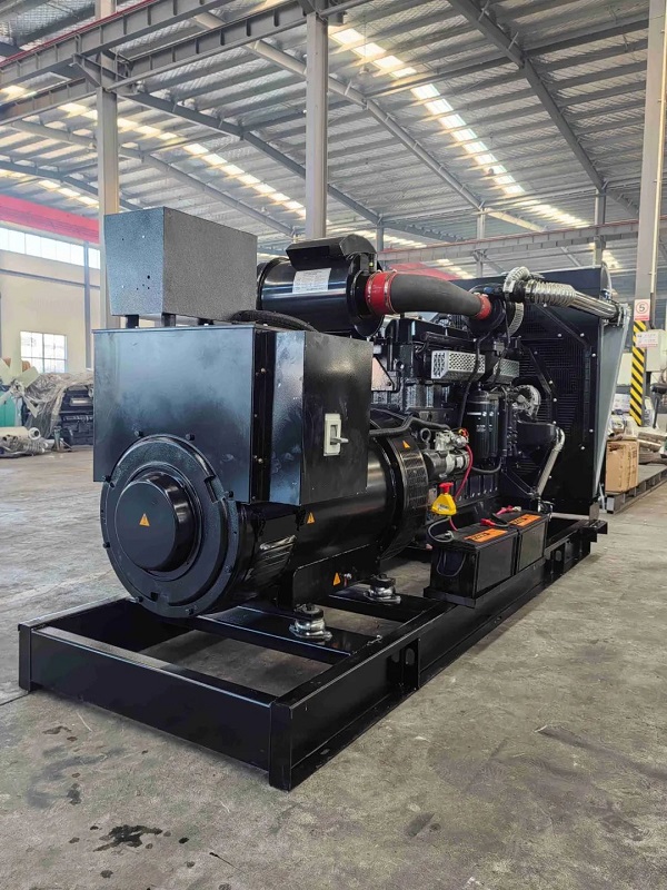
Diesel Generator
A diesel engine drives a generator, converting the energy from diesel fuel into electrical energy. Inside the cylinder of a diesel engine, clean air, filtered by the air filter, mixes thoroughly with high-pressure atomized diesel fuel injected by the fuel injector. As the piston moves upward, compressing the mixture, its volume decreases and the temperature rises rapidly until it reaches the diesel fuel’s ignition point. This ignites the diesel fuel, causing the mixture to combust violently. The rapid expansion of gases then forces the piston downward, a process known as ‘work’.
Gasoline Generator
A gasoline engine drives a generator, converting the chemical energy of gasoline into electrical energy. Inside the cylinder of a gasoline engine, a mixture of fuel and air undergoes rapid combustion, resulting in a swift expansion in volume that forces the piston downwards, performing work.
In both diesel and gasoline generators, each cylinder operates sequentially in a specific order. The force exerted on the piston is transformed by the connecting rod into rotational force, which drives the crankshaft. A brushless synchronous AC generator, coaxially mounted with the power engine’s crankshaft, allows the engine’s rotation to drive the generator’s rotor. Based on the principle of electromagnetic induction, the generator then produces an induced electromotive force, generating current through a closed load circuit.
Post time: Jul-28-2025